
CPC and Flow Chemistry: Connecting Continuous Synthesis with Purification
Flow chemistry enables chemical reactions to operate in a continuous stream, offering advantages in heat and mass transfer, process control and the handling of hazardous intermediates [1]. However, downstream purification often remains a separate batch operation, requiring intermediate collection, storage and repeated processing.
Centrifugal Partition Chromatography (CPC) offers an opportunity to integrate purification into continuous manufacturing workflows through its liquid–liquid separation principle and the possibility of continuous sample injection [2].
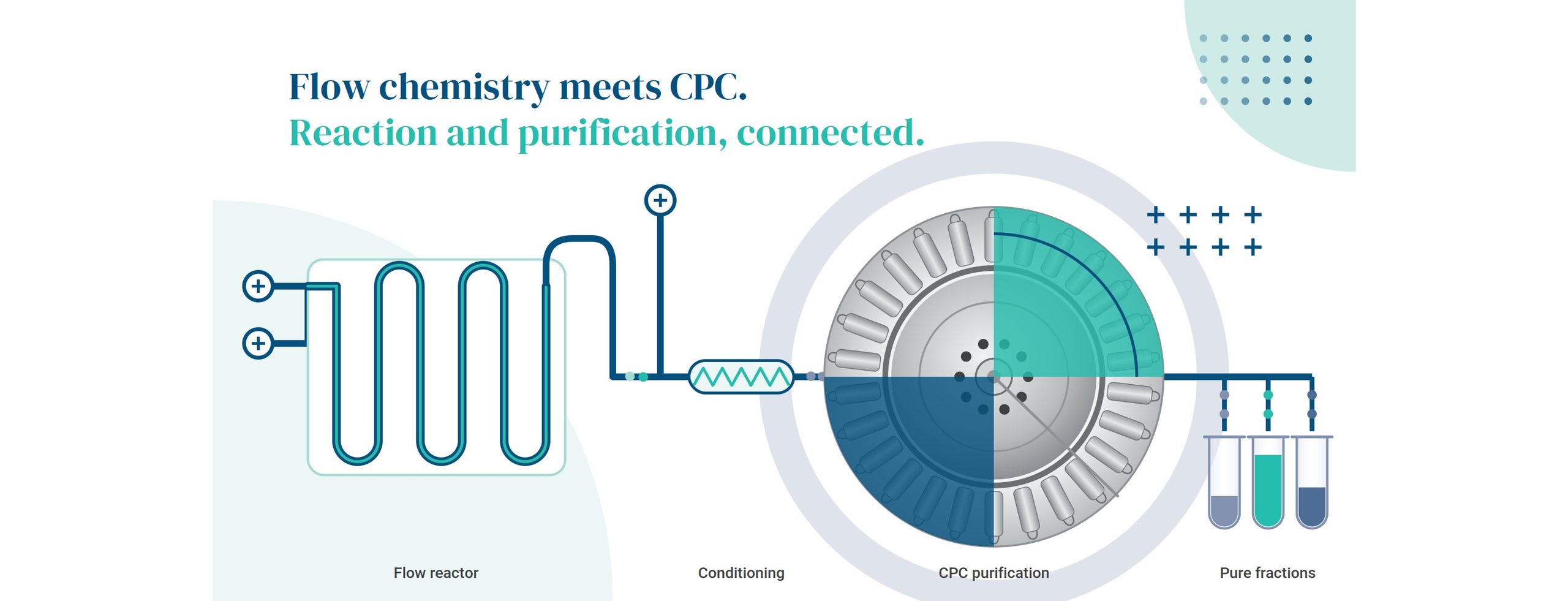
Why does CPC fit continuous reaction streams?
CPC separates compounds between two immiscible liquid phases. There is no silica or solid support, so several typical problems of column chromatography with crude reaction mixtures simply do not apply: no irreversible adsorption, no column fouling and no costly packing to replace. Three properties make it a natural fit for reactor output:
• It tolerates crude mixtures. The liquid stationary phase is replenished between runs, so a dirty, high-impurity stream does not progressively degrade it.
• It accepts high sample loads. Loading is governed by partitioning rather than by saturation of a solid surface, which suits concentrated reactor outputs.
• It extends a step flow processes already use. Many flow trains include in-line liquid–liquid extraction for work-up [3]; CPC works on the same partitioning principle, repeated many times along the rotor, so it continues the train rather than adding a foreign unit operation.
How you run the injection then depends on how continuous the process needs to be. Conventional CPC uses batch (single) injection; Multiple Dual-Mode operation enables repeated injection; and the dual-rotor Continuous CPC adds true continuous injection [4]. That range is what lets CPC be matched to a flow process at the level of integration each case needs, it is not that only the Continuous CPC can be used.
Different approaches to flow-CPC integration
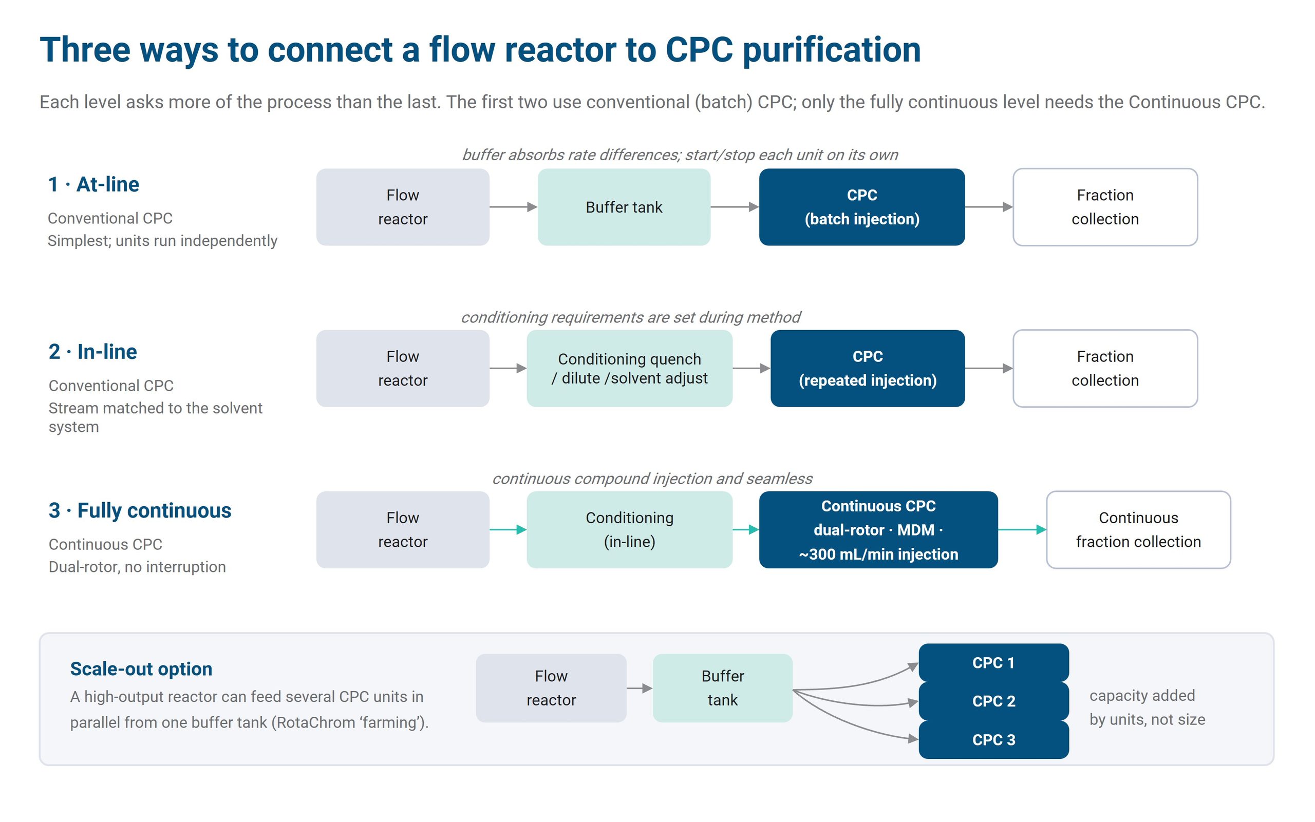
1. At-line, with a buffer tank
The reactor output goes into an intermediate vessel, and a conventional (batch) CPC draws from it at its own pace. This is the simplest option. The buffer absorbs differences in flow rate and lets each unit be started, stopped and optimised on its own.
2. In-line, with feed conditioning
A short conditioning step sits between reactor and CPC. It can include quenching, dilution, solvent adjustment or phase equilibration, so the stream matches the biphasic solvent system. The purification method sets the conditioning requirements, so these are defined during method development. This level still runs on conventional CPC, often with repeated injection.
3. Fully continuous
The conditioned stream is fed into the Continuous CPC without interruption. RotaChrom’s Continuous CPC is built on two interconnected GMP-rCPC units in a dual-rotor configuration, enabling continuous compound injection, seamless fraction collection and continuous manufacturing. It supports Multiple Dual-Mode (MDM), trapping-MDM and continuous-injection modes, with continuous sample injection at around 300 mL/min. This is the only level that requires the Continuous CPC rather than a conventional unit.
What determines successful integration?
Four things decide whether the integration works in practice.
1. Solvent compatibility. The reaction solvent must work with, or be easy to adapt to, the CPC biphasic system. If the reaction is designed with this in mind from the start, the conditioning step can be much simpler.
2. Flow matching. The reactor output rate, feed concentration and CPC throughput must balance. Where they do not, buffer volume covers the difference — or, for a high-output reactor, additional CPC units in parallel (scale-out) carry the extra load.
3. Solvent recovery. Continuous operation uses solvent continuously, so recycling has to be part of the design, not added later.
4. The whole-system view. RotaChrom’s process-engineering approach uses its proprietary Process Flow Calculator (PFC) to calculate ongoing flows, identify bottlenecks, evaluate buffer and evaporator capacities, and verify realistic operating times. In a connected reaction–purification train, the limiting step is often a peripheral, such as an evaporator or solvent-regeneration unit, rather than the reactor or the chromatography itself.Higher flow shortens each run. In CPC the limit is stationary-phase retention, so map retention against flow rate and rotation speed to find the optimum. Then look at the whole cycle, not only the elution. Stop runs once the target has eluted, and shorten equilibration where the process allows.
From continuous reaction to continuous manufacturing
Flow chemistry made reactions continuous; purification is the step that most often falls back to batch. CPC can close that gap because its liquid–liquid, support-free mechanism tolerates crude streams and high loads. Start where the process allows — at-line with a buffer tank on a conventional CPC — and move toward in-line conditioning and, where it pays off, a fully continuous train on the dual-rotor Continuous CPC. Match the architecture to the reactor with a whole-system calculation, and remember that the bottleneck is usually a peripheral, not the separation.
Connecting a reactor to purification? A RotaChrom feasibility study and process-engineering review size the buffer, conditioning, CPC and peripherals as one system before you build. Talk to our team.
References
[1] Plutschack MB, Pieber B, Gilmore K, Seeberger PH. The Hitchhiker’s Guide to Flow Chemistry. Chem Rev. 2017;117(18):11796–11893. doi:10.1021/acs.chemrev.7b00183
[2] Örkényi R, Éles J, Faigl F, Vincze P, Prechl A, Szakács Z, Kóti J, Greiner I. Continuous synthesis and purification by coupling a multistep flow reaction with centrifugal partition chromatography. Angew Chem Int Ed. 2017;56(30):8742–8745. doi:10.1002/anie.201703852
[3] Adamo A, Heider PL, Weeranoppanant N, Jensen KF. Membrane-based, liquid–liquid separator with integrated pressure control. Ind Eng Chem Res. 2013;52(31):10802–10808. doi:10.1021/ie401180t
[4] Viano R, Milani L, Örkényi R, Adamo A. Continuous separation and purification of chemical species by continuous liquid–liquid partition chromatography implemented with membrane-based phase separators. Org Process Res Dev. 2023;27(12):2296–2308. doi:10.1021/acs.oprd.3c00239
Frequently Asked Questions
+
Can CPC purify a crude reaction mixture directly from a flow reactor?
Often yes, after a simple conditioning step. Because the stationary phase is a liquid, CPC tolerates crude mixtures better than solid-phase columns.
+
Do I need a fully continuous CPC system to work with flow chemistry?
No. Many processes start with at-line purification and a buffer tank, then move to continuous injection once the method and flow balance are proven.
+
What limits a connected flow–CPC process?
Usually it is solvent compatibility, mismatched flow rates, or the capacity of peripherals such as evaporators and solvent recovery, not the chromatography itself.